Snip treatment facilities. SNiP sewage external networks and structures - requirements for the design and installation of the system
(as amended by Amendment No. 1, approved by the Resolution of the USSR Gosstroy
dated 05/28/1986 N 70)
Duration
January 1, 1986
Developed by Soyuzvodokanalproekt (G.M. Mironchik - topic leader; D.A. Berdichevsky, A.E. Vysota, L.V. Yaroslavsky) with the participation of VNIIVODGEO, Donetsk PromstroyNIIproekt and NIIOSP named after N.M. Gersevanov Gosstroy of the USSR, Research Institute of municipal water supply and water purification of the Academy of Public Utilities named after K.D. Pamfilov and Giprokommunvodokanal of the Ministry of Housing and Communal Services of the RSFSR, TsNIIEP engineering equipment Gosgrazhdanstroy, MosvodokanalNIIproekt and Mosinzhproekt of the Moscow City Executive Committee, Research and Design Institute of Urban Economics and UkrkommunNIIproekt of the Ministry of Housing and Communal Services of the Ukrainian SSR, Institute of Mechanics and Earthquake Engineering M.T. Urazbaev Academy of Sciences of the Uzbek SSR, Moscow Civil Engineering Institute. V.V. Kuibyshev Ministry of Higher Education of the USSR, Leningrad Civil Engineering Institute of the Ministry of Higher Education of the RSFSR.
Introduced by Soyuzvodokanalproekt Gosstroy USSR.
Prepared for approval by Glavtekhnormirovaniye Gosstroy of the USSR (B.V. Tambovtsev).
Agreed by the Ministry of Health of the USSR (letter of 10.24.1983 N 121-12 / 1502-14), the Ministry of Water Economy of the USSR (letter of 15.04.1985 N 13-3-05 / 366), the Ministry of Fishery of the USSR (letter of 04.26.1985 . N 30-11-9).
With the introduction of SNiP 2.04.03-85 "Sewerage. External networks and structures," SNiP II-32-74 "Sewerage. External networks and structures" expires.
These rules and regulations must be observed when designing newly built and reconstructed permanent outdoor sewage systems for settlements and national economy objects.
When developing sewage projects, one should be guided by the "Fundamentals of Water Legislation of the Union of Soviet Socialist Republics and Union Republics", comply with the "Rules for the Protection of Surface Water from Pollution from Wastewater" and the "Rules for the Sanitary Protection of Coastal Waters of the Sea" of the USSR Ministry of Water Economy, USSR Ministry of Agriculture and the USSR Ministry of Health, requirements of the "Regulations on of water protection and coastal stripes of the country's small rivers "and" Instructions on the procedure for approval and issuance of permits for special water use "of the USSR Ministry of Water and Water, as well as instructions on other regulatory documents, ut erzhdennyh or concerted USSR State.
1. General instructions
1.1. Sewerage facilities should be designed on the basis of approved schemes for the development and deployment of sectors of the national economy and industry, schemes for the development and distribution of productive forces in economic regions and union republics, general, basin and territorial schemes for the integrated use and protection of water, schemes and projects for district planning and urban development and other settlements, master plans of industrial nodes.
When designing, it is necessary to consider the feasibility of cooperating with sewage systems of objects regardless of their departmental affiliation, and also take into account the technical, economic and sanitary assessments of existing facilities, provide for the possibility of their use and intensification of their work.
Sewerage projects of facilities should be developed, as a rule, simultaneously with water supply projects with a mandatory analysis of the balance of water consumption and wastewater disposal. In this case, it is necessary to consider the possibility of using treated wastewater and rainwater for industrial water supply and irrigation.
1.2. In the rainwater drainage system, the most polluted part of the surface runoff generated during the period of rainfall, snowmelt and washing of road surfaces should be cleaned, i.e. not less than 70% of annual runoff for residential areas and sites of enterprises close to them in terms of pollution, and the total volume of runoff for sites of enterprises whose territory may be contaminated with specific substances with toxic properties or a significant amount of organic substances.
1.3. The main technical decisions made in the projects and the sequence of their implementation should be justified by comparing possible options. Technical and economic calculations should be performed according to those options whose advantages and disadvantages cannot be established without calculations.
The best option should be determined by the smallest amount of reduced costs, taking into account the reduction in labor costs, the consumption of material resources, electricity and fuel, as well as on the basis of sanitary and hygienic and fishery requirements.
1.4. When designing sewage networks and structures, progressive technical solutions, mechanization of labor-intensive work, automation of technological processes and maximum industrialization of construction and installation works through the use of prefabricated structures, standard and standard products and parts manufactured in factories and procurement workshops should be provided.
1.5. Wastewater treatment plants for industrial and rain sewers should, as a rule, be located on the territory of industrial enterprises.
1.6. When connecting sewer networks of industrial enterprises to the street or intra-quarter network of a settlement, outlets with control wells located outside the enterprises should be provided.
It is necessary to provide devices for measuring the discharge of waste water from each enterprise.
Combining the production wastewater of several enterprises is allowed after the control well of each enterprise.
1.7. The conditions and places for the release of treated wastewater and surface runoff to water bodies should be agreed with the bodies for regulating the use and protection of waters, the executive committees of local Councils of People's Deputies, bodies implementing state sanitary supervision, protection of fish stocks, and other bodies in accordance with Union law Soviet Socialist Republic and union republics, and places of release into navigable water bodies, watercourses and seas - also with the management bodies of the river fleet of the Union republics and the Ministry of the Marine ota.
1.8. When determining the reliability of the sewage system and its individual elements, it is necessary to take into account technological, sanitary and hygienic and water protection requirements.
In case of inadmissibility of interruptions in the operation of the sewage system or its individual elements, measures must be provided to ensure the uninterrupted operation of their work.
1.9. In the event of an accident or repair of one structure, the overload of the remaining structures of this purpose should not exceed 8 - 17% of their estimated capacity without reducing the efficiency of wastewater treatment.
1.10. Sanitary protection zones from sewage structures to the borders of residential buildings, sections of public buildings and food industry enterprises, taking into account their prospective expansion, should be taken:
from structures and pumping stations of the sewage system of settlements - according to the table. 1;
Consultant Plus: note.
SN 245-71 expired in connection with the publication of the Decree of the Gosstroy of the USSR of 05.05.1990 N 39. By the Decree of the Chief State Sanitary Doctor of the Russian Federation of 30.04.2003 N 88 from June 25, 2003 SP 2.2.1.1312-03 "Hygienic requirements for designing newly built and reconstructed industrial enterprises. "
from wastewater treatment plants and pumping stations of industrial sewage systems not located on the territory of industrial enterprises, both during independent treatment and pumping of industrial wastewater, and when they are combined with domestic wastewater treatment - in accordance with SN 245-71, the same as for production, from which sewage arrives, but not less than specified in tab. 1.
Table 1
─────────────────────────────┬────────────────────────────────────
Facilities │ Sanitary protection zone, m, at
│ estimated performance
│ structures, thousand m3 / day
├────────┬────────┬────────┬─────────
│ up to 0.2 │ St. 0.2 │ St. 5 │ St. 50
│ │ to 5 │ to 50 │ to 280
─────────────────────────────┼────────┼────────┼────────┼─────────
Mechanical and │ 150 │ 200 │ 400 │ 500
biological treatment with sludge │ │ │ │
high fermentation sites - │ │ │ │
precipitation, as well as individual │ │ │ │
but located silt │ │ │ │
platforms │ │ │ │
Mechanical and │ 100 │ 150 │ 300 │ 400
biological treatment with │ │ │ │
thermomechanical treatment │ │ │ │
precipitation in enclosed spaces │ │ │ │
Filtration fields │ 200 │ 300 │ 500 │ -
Agricultural irrigation fields │ 150 │ 200 │ 400 │ -
Biological ponds │ 200 │ 200 │ 300 │ 300
Circulation facilities│ 150 │ - │ - │ -
oxidizing channels │ │ │ │
Pumping stations │ 15 │ 20 │ 20 │ 30
Notes. 1. Sanitary protection zones of sewer
facilities with a capacity of over 280 thousand m3 / day., as well as
when deviating from accepted wastewater treatment technology and
sludge treatment are established in agreement with the main
sanitary and epidemiological departments of ministries
health care of the union republics.
2. Sanitary protection zones indicated in the table. 1 allowed
increase, but not more than 2 times in case of location
leeward residential development in relation to the sewage treatment plant
structures or reduce by no more than 25% if available
auspicious wind rose.
3. In the absence of silt sites in the territory
treatment facilities with a capacity of over 0.2 thousand m3 / day.
zone size should be reduced by 30%.
4. Sanitary protection zone from filtering fields up to
0.5 ha and from structures of mechanical and biological treatment on
biofilters with a productivity up to 50 m3 / day. should be taken
5. Sanitary protection zone from underground filtering fields
productivity less than 15 m3 / day. should be taken 15 m.
6. Sanitary protection zone from filtering trenches and sand
gravel filters should be taken 25 m away from septic tanks and
filter wells - 5 and 8 m, respectively, from aeration wells
complete oxidation plants with aerobic stabilization of sludge at
capacity up to 700 m3 / day. - 50 m.
7. The sanitary protection zone from the drain stations should be
take 300 m.
8. Sanitary protection zone from treatment facilities
surface water from residential areas should be taken
100 m, from pumping stations - 15 m, from treatment facilities
industrial enterprises - as agreed with the authorities
sanitary and epidemiological service.
9. Sanitary protection zones from sludge collectors should be
take depending on the composition and properties of the sludge as agreed
with the bodies of the sanitary-epidemiological service.
──────────────────────────────────────────────────────────────────
External sewer networks, according to SNiP, are used both in private country houses and in city apartments. Such a sewer system is very convenient, easy to operate and environmentally friendly. For its installation, you must familiarize yourself with the rules of use according to SNiP
Features and types of sewage systems SNiP
Sewerage network data is a branched pipeline that delivers wastewater from the premises (residential and non-residential) to special tanks. To ensure that sewage flows into the tank by gravity, the water pipes are installed under a slight slope.
The second version of the system involves the installation of pressure networks or the connection of a special pump.
Types of sewage systems according to SNiP
Depending on the purpose, sewer networks are divided:
- Household, which is divided into two types: central (serving the entire village) and autonomous (for one or more houses).
- Industrial (industrial treatment facilities).
- Storm, providing drainage after rain.
All of these species are divided into two subspecies:
- Outdoor (pipes are located on the street, including sewage treatment plants and structures).
- Internal (everything that is indoors).
According to the method of installation and laying of the SNiP pipeline, external communications are divided into several types:
In addition, sewer networks differ in other ways.
SNiP outdoor sewage systems
Outdoor communications can be located in various places and vary in purpose. There are several types of outdoor sewage networks:

Laying methods water pipes are determined in each case individually. This depends on several factors, such as bends and turns along the route, the level of groundwater passage, etc. It should be remembered that sewer pipes in any case are laid with a slope that varies depending on the diameter of the pipe. In some cases, it may be necessary to install a pump, drainage or manhole.
Component systems of external sewage
The sewage network consists of various elements that allow the transportation of waste water to wastewater treatment plants. In general, the sewage system includes the following details:
In addition, for the full operation of the sewage system, it is possible to use other additional elements.
Material for the manufacture of sewer pipes
The life of the pipeline depends on the choice of material. To date, the rules provide for the use of such materials as:
In rare cases, it is possible to use pipes made of glass or ceramic.

Since wastewater with all sewage immediately flows from the internal sewage system to the outside, the latter must cope with a huge amount of sewage at the same time.
Installation of an external sewage system
To ensure the reliability and long life of the sewer system during its installation, a number of rules must be observed.
SNiP requirements are based on factors such as:
- soil properties;
- climate features;
- ground water level;
- average volume of wastewater;
- distance to the nearest pumps and treatment plants.
It is also very important to observe the level of the slope of the pipe to ensure unhindered passage of wastewater by gravity. According to the requirements of SNiP, pipes must be laid under a certain slope in the sides of the well. The angle of inclination is determined by the diameter of the pipe and is 2-3 cm per meter of the pipeline.
Do not try to make a large slope: this, of course, will contribute to the rapid discharge of a huge amount of effluents, but it can lead to clogging of the system, since solid particles will be trapped in the pipe.
According to the requirements of SNiP, the size of the pipe for the external sewage of several houses included in the system should be at least 20 cm, and for one suburban cottage - 10–11 cm. When planning the installation of a sewage system, additional factors affecting future performance should be taken into account .
 Before proceeding directly to the installation of the sewage system, it is necessary to carry out preparatory work: to study the features of the soil, calculate all the elements, lay the route of the pipeline.
The first step is to determine the location of the collection well where the sewage will flow. In this case, the type of water collector is also taken into account: a septic tank that is able to not only accept, but also utilize pollution or an ordinary well.
The ideal location for the septic tank or well is the lowest place in the pipeline. If it is planned to clean the collection by means of a cesspool machine, it is better to place the well, for its comfortable maintenance, closer to the roadway.
A trench is excavated, which, if necessary, is supplied with additional details. The pipe joints must be carefully fixed and sealed. In order to prevent freezing of the water supply system in the winter, it is necessary to carry out thermal insulation. Then, the sewer system is connected to the treatment plant or collector and a trial run is performed.
The ditch is filled up and rammed only after a complete check of the entire structure as a whole.
Requirements for pipeline parts:
- Resistance to corrosion or providing additional protection.
- The presence of the foundation for the installation of the pipeline, taking into account the characteristics of the soil.
- Mandatory use of valves, plungers and other additional elements for pressure sewer networks.
- Installation of manholes only in places of slopes, intersections and bends of the water supply. The size of the well is determined by the diameter of the pipe and its length. Wells must have sewer manholes, stairs and fences.
- Rainwater receivers should be installed near pedestrian crossings, lowlands and crowded areas.
SNiP requirements for the sewerage of a private house
Sewerage in apartment buildings is taken for granted and almost invisible. Another thing is the removal of wastewater in a private house. Cesspools and street toilets are already considered a relic of the past, and many owners of suburban cottages are thinking about building a sewer system on their site. In order to independently mount and connect the sewage pipeline, it is necessary to know the building codes and rules, compliance with which will ensure a long and uninterrupted operation of the system.
Sewerage is laid immediately during the construction of a new house, but it’s also quite possible to equip the apartment with an outdoor toilet with street amenities.
 Private houses are divided into two types: those with the ability to connect to a central sewer system and those that cannot be connected.
The procedure for conducting intra-house installation work will be the same, the difference is only in the discharge of wastewater from the premises.
The sewage system of a private house, as well as a multi-unit, consists of sewer pipes and a riser connected to each other. Wastewater from toilets, bathtubs and sinks flows into horizontal pipes and flows into the sewage treatment plant or sewer in a riser. If the construction of the house is only planned, it is necessary to arrange the kitchen and bathroom near the exit point sewer pipe from home. If the cottage is multi-storey, then for ease of installation of the pipeline, bathrooms must be placed one above the other.
Pipe and plumbing installation
The toilet is attached to the riser separately. So that the drains do not fall into the pipes, the remaining elements should be located above the toilet.
To reduce the noise level, the risers can be closed in a box of drywall or wrapped with mineral wool. All necessary parts are attached to the pipes using knee siphons, in which there is always a small amount of water, which blocks the unpleasant odors of the system and prevents them from escaping.
Horizontal pipes that are under the floor, in the basement or basement, are connected to the riser with external pipes. Elements located outside the premises should be well insulated to prevent them from freezing during the cold season. At the exit from the house, all pipes are collected in one and connected to an external sewage system. Clamps are used as fasteners.
In order to prevent the appearance of specific odors when draining water, ventilation should be installed: the vertical riser is discharged to the roof, and its upper part must be well fixed not to be covered, but only protected from debris and precipitation. An aeration valve can also be installed to protect against odors.
 A trench is being prepared, the depth of which is determined by the level of soil freezing in a particular region. A sand cushion is necessarily laid at the bottom of the ditch, on which downpipes are mounted under a slight slope. If, due to the nature of the soil, it is impossible to dig a deep trench, the pipeline should be carefully insulated.
Private houses mainly have an autonomous sewage system, which can be of 4 types:
- Dry closet. Convenient, but requiring constant costs type of sewage.
- Cesspool. Cheap, but very uncomfortable to use look.
- Septic tank. Able not only to take wastewater, but also to clean them yourself.
- Sewage treatment plant. Cleaning is carried out using special bacteria. Quite effective, but at the same time - an expensive type of sewer system.
 Each of these options has its pros and cons. For example, a cesspool is best installed in areas that have a periodic pattern of use.
The treatment plant does not require constant care, but its disadvantage is its high cost. Of the proposed sewerage options for a private house, a septic tank can be ideal, which you can assemble yourself or buy ready-made.
So, following the rules of SNiP outdoor sewage networks, and following the recommendations made, you can easily install a sewer system in your home and thereby ensure yourself and your family a comfortable stay.
DEVELOPED by Soyuzvodokanalproekt (G.M. Mironchik - topic manager; D.A. Berdichevsky, A.E. Vysota, L.V. Yaroslavsky) with the participation of VNIIVODGEO, Donetsk PromstroyNIIproekt and NIIOSP them. N.M. Gersevanov Gosstroy of the USSR, Research Institute of municipal water supply and water purification Academy of Public Utilities named after KD Panfilov and Giprokommunvodokanal of the Ministry of Housing and Communal Services of the RSFSR, TsNIIEP of engineering equipment of the Gosgrazhdanstroy, MosvodokanalNIIproekt and Mosinzhproekt of the Moscow City Executive Committee, the Research and Design Institute of Urban Economics and the UkrkommunzhIIShimkost and Institute of Mechanical Engineering and the Institute of Mechanical Engineering and the Institute of Mechanical Engineering and the Institute of Mechanical Engineering and Social Development and Industrial Engineering M.T. Urazbaev of the Academy of Sciences of the Uzbek SSR, Moscow Institute of Civil Engineering V.V. Kuybysheva of the Ministry of Higher Education of the USSR, Leningrad Civil Engineering Institute of the Ministry of Higher Education of the RSFSR.
AGREED by the Ministry of Health of the USSR (letter of 10.24.83 N 121-12 / 1502-14), Ministry of Water Economy of the USSR (letter of 04.15.85 N 13-3-05 / 366), Ministry of Fishery of the USSR (letter of 26.04.85 N 30-11- 9).
With the introduction of SNiP 2.04.03-85 "Sewerage. External networks and structures," SNiP II-32-74 "Sewerage. External networks and structures" expires.
SNiP 2.04.03-85 "Sewerage. External networks and structures" introduced Amendment No. 1, approved by Gosstroy of the USSR dated May 28, 1986 No. 70 and entered into force on July 1, 1986. Items, tables, as amended are marked in these Building codes with the sign (K).
These rules and regulations must be observed when designing newly built and reconstructed permanent outdoor sewage systems for settlements and national economy objects.
When developing sewage projects, one should be guided by the "Fundamentals of Water Legislation of the Union of Soviet Socialist Republics and Union Republics", comply with the "Rules for the Protection of Surface Water from Pollution from Wastewater" and the "Rules for the Sanitary Protection of Coastal Waters of the Sea" of the USSR Ministry of Water Economy, USSR Ministry of Agriculture and the USSR Ministry of Health, requirements of the "Regulations on of water protection and coastal stripes of the country's small rivers "and" Instructions on the procedure for approval and issuance of permits for special water use "of the USSR Ministry of Water and Water, as well as instructions on other regulatory documents, ut erzhdennyh or concerted USSR State.
1.1. Sewerage facilities should be designed on the basis of approved schemes for the development and deployment of sectors of the national economy and industry, schemes for the development and distribution of productive forces in economic regions and union republics, general, basin and territorial schemes for the integrated use and protection of water, schemes and projects for district planning and urban development and other settlements, master plans of industrial nodes.
When designing, it is necessary to consider the feasibility of cooperating with sewage systems of objects regardless of their departmental affiliation, and also take into account the technical, economic and sanitary assessments of existing facilities, provide for the possibility of their use and intensification of their work.
Sewerage projects of facilities should be developed, as a rule, simultaneously with water supply projects with a mandatory analysis of the balance of water consumption and wastewater disposal. In this case, it is necessary to consider the possibility of using treated wastewater and rainwater for industrial water supply and irrigation.
1.2. In the rainwater drainage system, the most contaminated part of the surface runoff generated during the period of rainfall, snowmelt and washing of pavements should be treated, i.e. at least 70% of the annual runoff for residential areas and sites of enterprises close to them in terms of pollution, and the total volume of runoff for the sites of enterprises, the territory of which may be contaminated with specific substances with toxic properties or a significant amount of organic substances.
1.3. The main technical decisions made in the projects and the sequence of their implementation should be justified by comparing possible options. Technical and economic calculations should be performed according to those options whose advantages and disadvantages cannot be established without calculations.
The best option should be determined by the smallest amount of reduced costs, taking into account the reduction in labor costs, the consumption of material resources, electricity and fuel, as well as on the basis of sanitary and hygienic and fishery requirements.
1.4. When designing sewage networks and structures, progressive technical solutions, mechanization of labor-intensive work, automation of technological processes and maximum industrialization of construction and installation works through the use of prefabricated structures, standard and standard products and parts manufactured in factories and procurement workshops should be provided.
1.6. When connecting the sewer networks of industrial enterprises to the street or intra-quarter network of a settlement, outlets with control wells located outside the enterprises should be provided.
1.7. The conditions and places for the release of treated wastewater and surface runoff to water bodies should be agreed with the bodies for regulating the use and protection of waters, the executive committees of local Councils of People's Deputies, bodies implementing state sanitary supervision, protection of fish stocks, and other bodies in accordance with Union law Soviet Socialist Republic and union republics, and places of release into navigable water bodies, watercourses and seas - also with the management bodies of the river fleet of the Union republics and the Ministry of the Marine ota.
1.8. When determining the reliability of the sewage system and its individual elements, it is necessary to take into account technological, sanitary and hygienic and water protection requirements.
In case of inadmissibility of interruptions in the operation of the sewage system or its individual elements, measures must be provided to ensure the uninterrupted operation of their work.
1.9. In the event of an accident or repair of one structure, the overload of the remaining structures of this purpose should not exceed 8-17% of their estimated capacity without reducing the efficiency of wastewater treatment.
1.10. Sanitary protection zones from sewage structures to the borders of residential buildings, sections of public buildings and food industry enterprises, taking into account their prospective expansion, should be taken:
from wastewater treatment plants and pumping stations of industrial sewage systems not located on the territory of industrial enterprises, both during independent treatment and pumping of industrial wastewater, and when they are combined with domestic wastewater treatment - in accordance with SN 245-71, the same as for production, from which receives wastewater, but not less than those indicated in table 1.
Heavy rains and spring thaw for many homeowners are becoming a real problem. After all, the area after the rain turns into a kind of swamp, and regular flooding of the foundation and walls contribute to their destruction. Consider the main points of the construction of such a device as storm sewer - SNiP, GOST and other requirements that should be taken into account.
What is storm sewer? Storm sewers are called complex network engineering, which are used to collect and discharge moisture from the drained territory, which falls in the form of precipitation. For the construction of these schemes should be guided by the requirements of SNiP, which addressed the construction of external sewage networks.
The SNiP, which regulates the norms that external sewage networks must comply with, contains the necessary formulas for calculations during the design of the system, the requirements for materials, the depth of the pipes and other important aspects of construction are indicated.
Types of storm sewer
There are two types of storms:
- Point system.
- Linear system.
Point type stormwater drainage
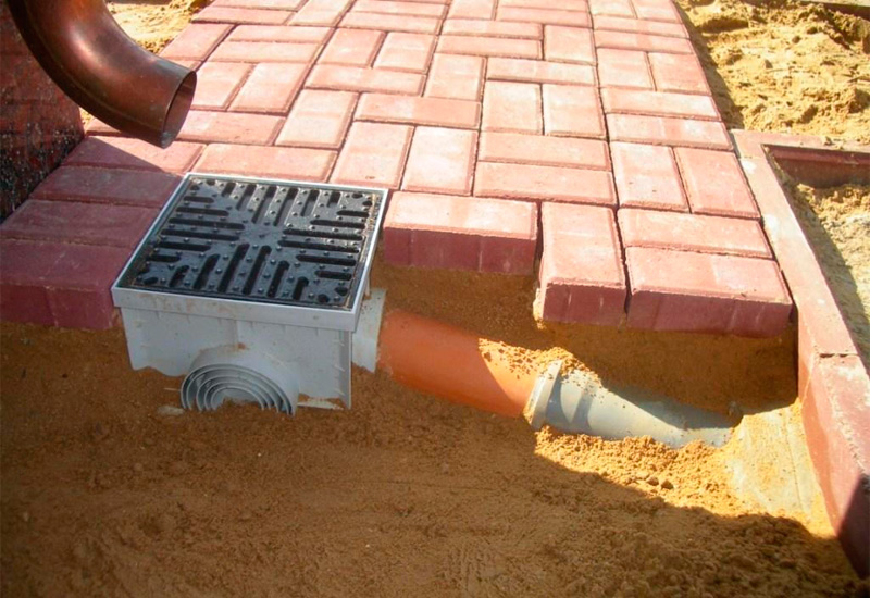
Point schemes are networks of storm water inlets and pipes connecting them. In order for the assembled circuit to be durable, safe and efficient, the technical conditions for storm sewers include the installation of protective gratings on storm water inlets, as well as the installation of special filters - sand traps.
Sewer storm linear type
A linear diagram is a network of channels that are designed to collect and transport water. According to the requirements of SNiP - storm sewage is mounted so that there is a bias towards the main collector.
Closed type storm sewers consist of a network of storm water inlets connected by pipes laid at a depth, through which water is discharged into the collector. For maintenance and monitoring of the system, it includes inspection wells with a diameter of 1 meter.
Advice! All aspects that will need to be taken into account during the development of the project and the construction of storm sewers are described in the regulatory document SNiP 2.04.01-85.
If, for some reason, when laying pipes, it is not possible to withstand minimum bias, then the system includes pumps for pumping liquid, since it cannot be moved by gravity.
Elements of storm sewers
As a rule, the following elements are included in the sewage network:
- Storm water inlets. This is one of the important elements of the system, the main function of which is the local collection of water from the surface of the earth.
- Door pallets. This is an analogue of storm water inlets, which are installed in front of the entrance groups at home or at the gate.
- Trays or gutters. Elements installed in ditches for water drainage. To allow water to move through them by gravity, a small slope of storm sewers is provided, directed towards the collector.
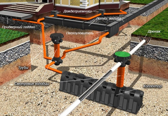
- Pipes. This element performs the same function as the trays, but is not laid in surface trenches, but underground.
- Sand traps. These are filter elements that prevent debris and soil particles from entering the drainage system.
- Viewing wells. Elements necessary to control the operation of the system.
Calculation of storm sewers
Before the start of the construction of the stormwater, you need to make the correct calculation of the storm sewer, for this you need to know:
- The average rainfall in this area.
- The drain area, that is, the area of \u200b\u200broofs, platforms and walkways with a waterproof coating.
- The properties of the soil on the site.
- The location of the already built underground utilities on the site.
You can calculate what the diameter of the storm sewer should be according to the formula:
Q \u003d q20 x F x Ψ
Designations in the formula:
Q - the amount of water that the system will have to divert.
q20 - precipitation intensity.
Advice! This value depends on the climatic conditions of the area, you can find its value in the tables on SNiP 2.04.03 - 85.
F is the surface area from which it is planned to discharge water.
Ψ - correction factor, which depends on the coating material of the site with which the water is collected.
Advice! The correction factor for the roof is 1.0, for paved areas and paths - 0.95, for concrete pavements - 0.85, for crushed stone coatings - 0.4 (and if the crushed stone is treated with bitumen, the coefficient will be 0.6).
Pipe Depth
The question of what should be the depth of the laying of storm sewers is widely discussed at building forums. Meanwhile, a quite understandable answer is given in SNiP 2.04.03-85 - the minimum depth of a storm sewer is determined by the experience of operating systems in this area.
Advice! As a rule, when operating in the middle lane and using pipes with diameters up to 500 mm, 30 cm is taken as the minimum depth. If pipes of a larger diameter are used to build a system such as storm sewers, the depth of their laying should not be less than 70 cm.
In order not to make complicated calculations and not worry about possible mistakes, it is best to find out what the depth of the people who are involved in the construction of storm sewers in practice should be. You can ask your neighbors if they have already finished building external drainage and storm sewer networks, or you can make inquiries with construction organizations working in this area.
Slope of storm pipes
In order to find out the minimum slope of storm sewers, you need to consider:
- Type of drainage;
- Pipe diameter;
- Surface coating.
When using pipes with a diameter of 200 mm, the slope should be 0.7 cm per meter of pipe length. If pipes with a cross section of 150 mm were used, the slope should be 0.8 cm per meter. In case of urgent need, SNiP 2.04.03-85 has a direct indication that in certain sections of the network the minimum slope can be slightly reduced:

- up to 0.5 cm per meter when using pipes with a size of 200 mm;
- up to 0.7 cm per meter for pipes with a diameter of 150 mm.
Thus, if local conditions force this to be done, it is possible to “save” up to 2 mm per meter of pipeline length. Do not forget that SNiP regulates not only the minimum, but also the maximum slope of the pipeline. It should not exceed 1.5 cm per meter of pipe.
If you exceed this indicator, then the risk of clogging the structure will increase. The fact is that if the slope is greater than normal, the water quickly leaves, and the sand contained in it settles, as a result, the inner surface of the pipe quickly silts.
Construction of storm sewers
In general, installation work on the installation of storm storms takes place in the same way as when laying the outer pipelines of ordinary sewers.
The choice of pipes for the underground part of the pipeline
If external stormwater networks are mounted, SNiP allows the use of the following types of pipes:
- Asbestos-cement;
- Steel;
- Plastic
Asbestos cement is a traditional material used for the construction of external sewage pipelines, including stormwater. The disadvantages of the material include its high fragility and considerable weight (a meter of a pipe with a diameter of 100 mm weighs more than 24 kg). Steel pipes they have much less weight (a meter of pipe weighs about 10 kg), but they are prone to corrosion, so it is unprofitable to use them for the construction of stormwater.
Recently, plastic pipes have been used to construct stormwater. They are light (a meter weighs no more than 5 kg), but are durable and resistant to corrosion. In addition, they are easy to connect, no welding required. Can be used:
- PVC pipes, if external networks are mounted, then for their construction you need to use a special type of pipe, they are painted in orange;
- Layered polymer pipes. Today is the best option. These pipes have a smooth inner surface, so hydraulic resistance does not occur.
Roof installation
The work goes like this:
- In the ceilings, holes are arranged for installing storm water inlets, all junctions are carefully sealed.
- Outflow pipes are strengthened during the construction of a point system or trays - during the installation of a linear stormwater system.
- Install sewage risers or pipes.
- A water discharge unit is going to the collector or discharge into the tray systems.
- All devices are attached to walls and ceilings with clamps. Places for installing clamps are planned in advance, not forgetting to observe the recommended values \u200b\u200bof the slopes.
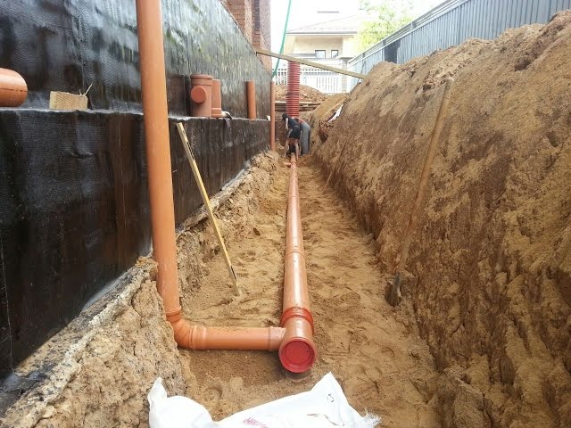
Underground installation
- Installation begins with the installation of trenches. During the construction of systems such as storm sewers, the depth of laying is most often determined not by the freezing depth, but by the experience of operating the systems at the construction site.
- The trenches are excavated with a slope, that is, their depth should gradually increase.
- At the bottom of the trenches, a sand pillow is made, the layer height is 20 cm.
- The foundation pit is being prepared for installing the collector.
- Pipes should be laid in the prepared ditches; pipe connections to each other and their connection to the collector are carried out using conventional fittings.
- If the sewer network consists of a single branch with a length of more than 10 meters, then in the middle it is worth planning to install a viewing well. Such wells should be placed at the branching points of networks.
- Sand collectors are installed at the junction of the water inlets and the storm pipe systems.
- Now it remains to backfill the trenches and cover the open structures (trays) with trellises on top.
The need to create security zones
Few people know that there is such a thing as a sewage protection zone, including a storm, and meanwhile, SNiP stipulate that a security zone of a certain size be organized near the pipes. So, the storm protection zone provides an indent from the walls of the pipe in each direction for 5 meters. The security zone is a place where it is prohibited:
- Build permanent or temporary structures.
- Dispose of landfills.
- Arrange parking.
- Plant trees or bushes less than three meters from the pipe.
- Block free access to manholes.
So, the installation of a rainwater drainage system is a necessary measure in the improvement of the site. When constructing such systems, it is necessary to strictly comply with the requirements and rules that are formulated in regulatory documents - construction and sanitary rules.
Approved and enforced
Order of the Ministry
regional development
Russian Federation
(Ministry of Regional Development of Russia)
dated December 29, 2011 N 635/11
SET OF RULES
SEWERAGE. EXTERNAL NETWORKS AND STRUCTURES
UPDATED EDITORIAL
SNiP 2.04.03-85
Seewerage. Pipelines and wastewater treatment plants
SP 32.13330.2012
Date of introduction
January 1, 2013
Foreword
The goals and principles of standardization in the Russian Federation are established by the Federal Law of December 27, 2002 N 184-ФЗ "On Technical Regulation", and the development rules - by the Decree of the Government of the Russian Federation of November 19, 2008 N 858 "On the procedure for the development and approval of codes of practice "
Rule Set Information
1. Contractors - LLC "ROSEKOSTROY", OJSC "Research Center" Construction ".
2. Submitted by the Technical Committee for Standardization TC 465 "Construction".
3. Prepared for approval by the Department of Architecture, Construction and Urban Policy.
4. Approved by Order of the Ministry of Regional Development of the Russian Federation (Ministry of Regional Development of Russia) dated December 29, 2011 N 635/11 and entered into force on January 1, 2013.
5. Registered by the Federal Agency for Technical Regulation and Metrology (Rosstandart). Revision of SP 32.13330.2010 "SNiP 2.04.03-85. Sewerage. External networks and structures."
Information on amendments to this set of rules is published in the annually published information index "National Standards", and the text of the changes and amendments is published in the monthly published information signs "National Standards". In case of revision (replacement) or cancellation of this set of rules, the corresponding notification will be published in the monthly published information index "National Standards". Relevant information, notification and texts are also posted in the public information system - on the official website of the developer (Ministry of Regional Development of Russia) on the Internet.
Introduction
Updating performed by ROSEKOSTROY 000 and SIC Construction, responsible executors: G.M. Mironchik, A.O. Dushko, L.L. Menkov, E.N. Zhirov, S.A. Kudryavtsev (LLC "ROSEKOSTROY"), M.I. Alekseev (SPbGASU), D.A. Danilovich (OJSC MosvodokanalNIIProekt), R.Sh. Neparidze (LLC Giprokommunvodokanal), M.N. Orphan (TsNIIEP Engineering Equipment OJSC), V.N. Shvetsov (NII VODGEO OJSC).
1 area of \u200b\u200buse
This set of rules establishes design standards for newly built and reconstructed permanent outdoor sewage systems for municipal and close to them in terms of the composition of industrial wastewater, as well as rain sewer.
This set of rules does not apply to sewage systems of greater capacity (more than 300 thousand m3 / day).
This set of rules provides links to the following regulatory documents:
SP 5.13130.2009. Fire protection systems. Automatic fire alarm and fire extinguishing installations. Norms and design rules
SP 12.13130.2009. Definition of the category of premises, buildings and outdoor installations for explosion and fire hazard
SP 14.13330.2011 "SNiP II-7-81 *. Construction in seismic areas"
SP 21.13330.2012 "SNiP 2.01.09-91. Buildings and structures in the developed areas and subsidence soils"
SP 25.13330.2012 "SNiP 2.02.04-88. Foundations and foundations on permafrost soils"
SP 28.13330.2012 "SNiP 2.03.11-85. Protection of building structures from corrosion"
SP 30.13330.2012 "SNiP 2.04.01-85 *. Internal water supply and sewerage of buildings"
SP 31.13330.2012 "SNiP 2.04.02-84 *. Water supply. External networks and structures"
SP 38.13330.2012 "SNiP 2.06.04-82 *. Loads and impacts on hydraulic structures (wave, ice and from ships)"
SP 42.13330.2011 "SNiP 2.07.01-89 *. Urban planning. Planning and development of urban and rural settlements"
SP 43.13330.2012 SNiP 2.09.03-85. Construction of industrial enterprises
SP 44.13330.2011 "SNiP 2.09.04-87 *. Administrative and domestic buildings"
SP 62.13330.2011 "SNiP 42-01-2002. Gas distribution systems"
SP 72.13330.2012 "SNiP 3.04.03-85. Protection of building structures and structures from corrosion"
SP 104.13330.2011 "SNiP 2.06.15-85. Engineering protection of territories from flooding and flooding"
Consultant Plus: note.
JV 131.13330.2011, referred to in this document, was subsequently approved and published with the number of JV 131.13330.2012.
SP 131.13330.2011 "SNiP 23-01-99 *. Construction climatology"
GOST R 50571.1-2009. Low voltage electrical installations
GOST R 50571.13-96. Electrical installations of buildings. Part 7. Requirements for special electrical installations. Section 706. Cramped Rooms with Conductive Floors, Walls, and Ceilings
GOST R 50571.15-97. Electrical installations of buildings. Part 5. Selection and installation of electrical equipment. Chapter 52. Electrical Wiring
GOST 12.1.005-88. Occupational safety standards system. General hygiene requirements for workplace air
GOST 17.1.1.01-77. Protection of Nature. Hydrosphere. Use and protection of water. Key Terms and Definitions
GOST 14254-96. Degrees of protection provided by enclosures (IP code)
GOST 15150-69 *. Machines, devices and other technical products. Versions for different climatic regions. Categories, operating conditions, storage and transportation regarding the impact of climatic environmental factors
GOST 19179-73. Hydrology of sushi. Terms and Definitions
GOST 25150-82. Sewerage. Terms and Definitions.
Note. When using this set of rules, it is advisable to check the validity of reference standards and classifiers in the public information system - on the official website of the national standardization body of the Russian Federation on the Internet or on the annually published information index "National Standards", which is published as of January 1 of this year , and according to the corresponding monthly published information indexes published in the current year. If the referenced document is replaced (changed), then when using this set of rules should be guided by the replaced (changed) document. If the referenced material is canceled without replacement, the provision in which the link to it is given applies to the extent not affecting this link.
3. Terms and definitions
In this set of rules, terms and definitions are used in accordance with GOST 17.1.1.01, GOST 25150, GOST 19179, as well as terms with the corresponding definitions given in Appendix A.
4. General
4.1. The selection of schemes and systems of sewage facilities should be made taking into account the requirements for wastewater treatment, climatic conditions, terrain, geological and hydrological conditions, the current situation in the drainage system and other factors.
4.2. When designing, it is necessary to consider the feasibility of cooperating with sewage systems of objects, take into account the economic and sanitary assessments of existing structures, provide for the possibility of their use and the intensification of their work.
4.3. Treatment of industrial and municipal wastewater is allowed to be carried out jointly or separately, depending on their nature and subject to maximum reuse.
4.4. Projects of sewage facilities, as a rule, should be linked to the scheme of their water supply, with a mandatory consideration of the possibility of using treated wastewater and rainwater for industrial water supply and irrigation.
4.5. When choosing a sewage scheme for industrial enterprises, it is necessary to consider:
the possibility of reducing the volume of polluted wastewater generated in technological processes due to the introduction of non-waste and waterless production, the installation of closed water systems, the use of air cooling methods, etc .;
the possibility of local treatment of wastewater flows in order to extract individual components;
the possibility of consistent use of water in various technological processes with different requirements for its quality;
conditions for the discharge of industrial wastewater into water bodies or into the sewage system of a settlement or other water user;
conditions for the disposal and use of sludge and waste generated during wastewater treatment.
4.6. Combining the flows of industrial wastewater with various pollutants is allowed when it is advisable to co-treat them.
In this case, it is necessary to take into account the possibility of chemical processes in the communications with the formation of gaseous or solid products.
4.7. When connecting the sewer networks of subscribers that are not related to the housing stock to the networks of the settlement, it is necessary to provide releases with control wells located outside the territory of the subscribers.
It is necessary to provide devices for measuring the discharge of wastewater from each enterprise, if the subscriber has a substantially open water balance, at least in the following cases:
if the subscriber is not connected to a centralized water supply system or has (or may have) water supply from several sources;
if during the production process more than 5% of the water consumption consumed from the water supply is added or withdrawn.
Combining the production wastewater of several enterprises is allowed after the control well of each enterprise.
4.8. Industrial wastewater to be disposed of and treated together with household wastewater of a settlement must meet current requirements for the composition and properties of wastewater taken into the sewage system of a settlement.
Industrial waste water that does not meet the specified requirements must be pre-treated. The degree of such treatment should be agreed upon with the organization (organizations) operating the sewage system and treatment facilities of the settlement (or, in the absence thereof, with the organization designing this sewage system).
4.9. It is forbidden to discharge into water bodies untreated to the established standards rain, melt and irrigation water, which is organized away from residential areas and sites of enterprises.
4.10. When designing wastewater treatment plants for general alloy and semi-divided sewage systems that carry out the joint disposal of all types of wastewater, including surface runoff from residential areas and enterprise sites, one should be guided by the instructions in this set of rules, as well as other regulatory documents governing the operation of these systems, including including regional.
4.11. The most polluted part of the surface runoff, which is formed during periods of rainfall, snowmelt and from the washing of road surfaces, in the amount of at least 70% of the annual runoff volume for residential areas and sites of enterprises close to them in terms of pollution, and all the volume of runoff from the sites of enterprises whose territory may be contaminated with specific substances with toxic properties or a significant amount of organic substances.
For the majority of settlements in the Russian Federation, these conditions are fulfilled when calculating treatment facilities for receiving runoff from low-intensity, often repeated rains with a period of one-time excess of the calculated rain intensity of 0.05 - 0.1 years.
4.12. Surface wastewater from industrial areas, construction sites, warehouses, car farms, as well as especially polluted areas located in residential areas of cities and towns (gas stations, parking lots, bus stations, shopping centers), before discharge into rain sewer or a centralized municipal sewage system should be treated at a local treatment plant.
4.13. When determining the conditions for the release of surface runoff from residential areas and enterprise sites into water bodies, one should be guided by the standards of the Russian Federation for the conditions for the discharge of urban wastewater.
The choice of the scheme of diversion and treatment of surface runoff, as well as the design of treatment facilities, is determined by its qualitative and quantitative characteristics, conditions of disposal and is carried out on the basis of assessing the technical feasibility of implementing a particular option and comparing technical and economic indicators.
4.14. When designing rainwater drainage facilities in populated areas and industrial sites, it is necessary to consider the option of using treated wastewater for industrial water supply, irrigation or irrigation.
4.15. The main technical solutions used in the projects, the sequence of their implementation should be justified by a technical and economic comparison of possible options, taking into account sanitary and hygienic and environmental requirements.
4.16. When designing sewage networks and structures, progressive technical solutions, mechanization of labor-intensive work, automation of technological processes, industrialization of construction and installation works through the use of structures, structures and factory-made products, etc. should be provided.
It should also include measures for energy conservation, as well as for the maximum possible use of secondary energy resources from wastewater treatment plants, the disposal of treated water and sludge.
It is necessary to ensure appropriate safety and sanitary-hygienic working conditions during the operation and implementation of preventive and repair work.
4.17. The location of the sewage system and the passage of communications, as well as the conditions and places for the release of treated wastewater and surface runoff into water bodies, must be agreed with local authorities, organizations that carry out state sanitary supervision and protection of fish stocks, as well as with other bodies, in accordance with the legislation of the Russian Federation, and the places of release into navigable water bodies and seas - with the relevant authorities of the river and sea fleet.
4.18. The reliability of the sewage system is characterized by the preservation of the required estimated throughput and the degree of wastewater treatment when the wastewater flow rate and composition of pollutants changes (within certain limits), conditions for their discharge into water bodies, in the event of power outages, possible accidents in communications, equipment and structures, the production of scheduled repair work, situations related to special environmental conditions (seismic, subsidence of soils, permafrost, etc.).
4.19. To ensure uninterrupted operation of the sewage system, the following measures should be provided:
appropriate reliability of power supply of sewage facilities (two independent sources, stand-alone autonomous power station, storage batteries, etc.);
duplication of communications, arrangement of bypass lines and bypasses, switching on parallel pipelines, etc .;
arrangement of emergency (buffer) tanks with subsequent pumping out of them in normal mode;
sectioning of parallel working structures, with the number of sections providing the necessary and sufficient effectiveness of the action when one of them is disconnected for repair or maintenance;
reservation of working equipment for one purpose;
providing the necessary margin of power, throughput, capacity, strength, etc. equipment and facilities (determined by technical and economic calculations);
determination of the allowable reduction in system capacity or the efficiency of wastewater treatment in emergency situations (as agreed with the supervisory authorities).
The application of the above measures should be studied during the design taking into account the responsibility of the object.
4.20. Sanitary protection zones from sewage structures to the borders of residential buildings, sections of public buildings and food industry enterprises, taking into account their prospective expansion, should be adopted in accordance with sanitary standards, and cases of deviation from them should be agreed with the sanitary and epidemiological surveillance authorities.
5. The estimated costs of urban wastewater.
Hydraulic calculation of sewer networks.
Unit costs, unevenness coefficients
and estimated wastewater costs
5.1. General directions
5.1.1. When designing sewage systems in settlements, the calculated average daily average (per year) of sewage from residential buildings should be taken equal to the calculated average daily average (per year) of water consumption according to SP 31.13330, excluding water consumption for irrigation of territories and green spaces.
5.1.2. Specific wastewater to determine the estimated costs of wastewater from individual residential and public buildings, if necessary, account for concentrated costs should be taken in accordance with SP 30.13330.
5.1.3. The amount of wastewater of industrial enterprises and the coefficients of unevenness of their inflow should be determined by technological data with an analysis of the water balance in terms of possible water circulation and reuse of wastewater, in the absence of data - by the integrated norms of water consumption per unit of output or raw materials or according to similar enterprises.
From the total amount of wastewater of enterprises, it is necessary to single out the costs accepted in the sewers of a settlement or other water user.
5.1.4. Specific drainage in non-canalized areas should be taken 25 l / day per inhabitant.
5.1.5. The estimated average daily wastewater flow rate in the village should be determined as the sum of the costs established in 5.1.1 - 5.1.4.
The amount of wastewater from local industrial enterprises serving the population, as well as unaccounted for expenses, may (if justified) be additionally accepted in the amount of 6-12% and 4-8% of the total average daily drainage of the settlement (if justified).
5.1.6. Estimated daily wastewater costs should be taken as the product of the average daily (for the year) consumption according to 5.1.5 by the daily unevenness coefficients, adopted in accordance with SP 31.13330.
5.1.7. Estimated total maximum and minimum wastewater costs, taking into account daily, hourly and intra-hourly irregularities, should be determined by computer simulation of wastewater systems that take into account schedules of wastewater inflow from buildings, residential areas, industrial enterprises, the length and configuration of networks, the availability of pumping stations, etc. d., or according to the actual water supply schedule during the operation of similar facilities.
In the absence of these data, it is allowed to take general coefficients (maximum and minimum) according to table 1.
Table 1
Estimated total maximum and minimum costs
sewage, taking into account daily, hourly
and intra-hourly unevenness
Total ratio
flow irregularities
wastewater Average wastewater consumption, l / s
5 10 20 50 100 300 500 1000 5000
and more
Maximum at 1%
security 3.0 2.7 2.5 2.2 2.0 1.8 1.75 1.7 1.6
Minimum at 1%
security 0.2 0.23 0.26 0.3 0.35 0.4 0.45 0.51 0.56
Maximum at 5%
security 2.5 2.1 1.9 1.7 1.6 1.55 1.5 1.47 1.44
Minimum at 5%
security 0.38 0.46 0.5 0.55 0.59 0.62 0.66 0.69 0.71
Notes. 1. General wastewater inflow rates given in
table, it is allowed to take with the number of production wastewater
water not exceeding 45% of the total flow.
2. With an average wastewater flow rate of less than 5 l / s, the maximum
non-uniformity coefficient is accepted 3.
3. 5% security implies a possible increase
(decrease) in consumption on average 1 time per day, 1% - 1 time per
during 5-6 days.
5.1.8. The estimated costs for networks and structures for the supply of sewage by pumps should be taken equal to the productivity of pumping stations.
5.1.9. When designing drainage communications and facilities for wastewater treatment, one should consider the feasibility and sanitary-hygienic possibility of averaging the estimated costs of wastewater.
5.1.10. Sewerage facilities should be designed to allow the passage of the total estimated maximum flow rate (determined by 5.1.7) and the additional influx of surface and groundwater, disorganized into gravity sewer networks through leaks in manhole covers and due to groundwater infiltration.
The magnitude of the additional inflow, l / s, is determined on the basis of special surveys or data on the operation of similar facilities, and in their absence, by the formula
where L is the total length of gravity pipelines to the calculated structure (pipeline alignment), km;
- the value of the maximum daily amount of precipitation, mm (according to SP 131.13330).
Verification calculation of gravity pipelines and channels with a cross-section of any shape for the passage of increased flow should be carried out when filling 0.95 height.
5.2. Hydraulic calculation of sewer networks
5.2.1. Hydraulic calculation of gravity sewer pipelines (trays, channels) should be performed at the estimated maximum second flow rate of wastewater according to tables, graphs and nomograms. The main requirement in the design of gravity collectors is to pass the estimated costs at self-cleaning speeds of the transported wastewater.
5.2.2. Hydraulic calculation of pressure sewer pipelines should be made in accordance with SP 31.13330.
5.2.3. Hydraulic calculation of pressure pipelines transporting raw and fermented sludge, as well as activated sludge, should be carried out taking into account the mode of movement, physical properties and characteristics of the composition of the sediments. At a moisture content of 99% or more, the sediment obeys the laws of movement of the waste fluid.
5.2.4. The hydraulic slope i when calculating pressure head sludges with a diameter of 150 - 400 mm is determined by the formula
where is the moisture content of the sediment,%;
V is the sediment speed, m / s;
D is the diameter of the pipeline, m;
- diameter of the pipeline, cm;
- coefficient of resistance to friction along the length, determined by the formula
For pipelines with a diameter of 150 mm, the value should be increased by 0.01.
5.3. Smallest pipe diameters
5.3.1. The smallest pipe diameters of gravity networks should be taken, mm:
for a street network - 200, an intra-quarter network, a network of domestic and industrial sewage - 150;
for rain street network - 250, intra-quarter - 200.
The smallest diameter of pressure pipes is 150 mm.
Notes. 1. In settlements with a wastewater flow rate of up to 300 m3 / day for the street network, the use of pipes with a diameter of 150 mm is allowed.
2. For the production network, with appropriate justification, the use of pipes with a diameter of less than 150 mm is allowed.
5.4. Estimated speeds and filling of pipes and channels
5.4.1. In order to avoid siltation of sewer networks, the estimated speed of the wastewater should be taken depending on the degree of filling of pipes and channels and the size of suspended solids contained in the wastewater.
The minimum speed of movement of wastewater in domestic and rainwater networks with the highest estimated filling of pipes should be taken according to table 2.
table 2
Estimated minimum wastewater speeds
depending on the highest degree of tube filling
in domestic and rainwater networks
│ Diameter, mm │ Velocity V, m / s, when filling H / D │
│ │ min │
│ ├───────────┬───────────┬───────────┬───────────┤
│ │ 0,6 │ 0,7 │ 0,75 │ 0,8 │
│150 - 250 │ 0,7 │ - │ - │ - │
├─────────────────────────┼───────────┼───────────┼───────────┼───────────┤
│300 - 400 │ - │ 0,8 │ - │ - │
├─────────────────────────┼───────────┼───────────┼───────────┼───────────┤
│450 - 500 │ - │ - │ 0,9 │ - │
├─────────────────────────┼───────────┼───────────┼───────────┼───────────┤
│600 - 800 │ - │ - │ 1,0 │ - │
├─────────────────────────┼───────────┼───────────┼───────────┼───────────┤
│900 │ - │ - │ 1,10 │ - │
├─────────────────────────┼───────────┼───────────┼───────────┼───────────┤
│1000 - 1200 │ - │ - │ - │ 1,20 │
├─────────────────────────┼───────────┼───────────┼───────────┼───────────┤
│1500 │ - │ - │ - │ 1,30 │
├─────────────────────────┼───────────┼───────────┼───────────┼───────────┤
│St. 1500 │ - │ - │ - │ 1.50 │
├─────────────────────────┴───────────┴───────────┴───────────┴───────────┤
│ Notes. 1. For production wastewater, the lowest speeds│
│ Accept in accordance with the guidelines for building design │
│ enterprises of individual industries or operational │
│ data. │
│ 2. For industrial wastewater similar in nature to suspended │
│ substances to household, take the lowest speeds as for domestic sewage │
Water. │
│ 3. For rain sewage at P \u003d 0.33 years, the lowest speed│
│ Take 0.6 m / s. │
5.4.2. The minimum estimated speed of clarified or biologically treated wastewater in trays and pipes is allowed to take 0.4 m / s.
The highest estimated speed of wastewater should be taken, m / s: for metal and plastic pipes - 8 m / s, for non-metallic (concrete, reinforced concrete and chrysotile cement) - 4 m / s, for rain sewage - 10 and 7 m / s, respectively.
5.4.3. The estimated speed of movement of unclarified wastewater in the siphons must be taken at least 1 m / s, while in places where the wastewater approaches the siphon, the speed should be no more than the speeds in the siphon.
5.4.4. The lowest calculated speeds of movement of raw and fermented sediments, as well as compacted activated sludge in pressure pipes, should be taken according to table 3.
Table 3
Estimated minimum raw speeds
and fermented sediments as well as compacted
activated sludge in pressure pipes
┌─────────────────────────┬───────────────────────────────────────────────┐
│ Sediment humidity,% │ V, m / s, at │
│ │ min │
│ ├───────────────────────┬───────────────────────┤
│ │ D \u003d 150 - 200 mm │ D \u003d 250 - 400 mm │
│ 98 │ 0,8 │ 0,9 │
├─────────────────────────┼───────────────────────┼───────────────────────┤
│ 97 │ 0,9 │ 1,0 │
├─────────────────────────┼───────────────────────┼───────────────────────┤
│ 96 │ 1,0 │ 1,1 │
├─────────────────────────┼───────────────────────┼───────────────────────┤
│ 95 │ 1,1 │ 1,2 │
├─────────────────────────┼───────────────────────┼───────────────────────┤
│ 94 │ 1,2 │ 1,3 │
├─────────────────────────┼───────────────────────┼───────────────────────┤
│ 93 │ 1,3 │ 1,4 │
├─────────────────────────┼───────────────────────┼───────────────────────┤
│ 92 │ 1,4 │ 1,5 │
├─────────────────────────┼───────────────────────┼───────────────────────┤
│ 91 │ 1,7 │ 1,8 │
├─────────────────────────┼───────────────────────┼───────────────────────┤
│ 90 │ 1,9 │ 2,1 │
└─────────────────────────┴───────────────────────┴───────────────────────┘
5.4.5. The highest speeds of rainfall and allowed to be discharged into the reservoirs of industrial wastewater in canals should be taken according to table 4.
Table 4
The highest speeds of rain and permissible
to drain into the reservoirs of industrial wastewater in canals
┌────────────────────────────────┬────────────────────────────────────────┐
│ Ground or type of channel attachment │ Maximum speed in the channels, │
│ │ m / s, with a flow depth of 0.4 to 1 m │
│ Fastening with concrete slabs │ 4 │
├────────────────────────────────┼────────────────────────────────────────┤
│Limestones, medium sandstones │ 4 │
├────────────────────────────────┼────────────────────────────────────────┤
│Option: │ │
│ flat │ 1 │
│ about the wall │ 1.6 │
├────────────────────────────────┼────────────────────────────────────────┤
│ Paving: │ │
│ single │ 2 │
│ double │ 3 - 3,5 │
├────────────────────────────────┴────────────────────────────────────────┤
│ Note. With a flow depth of less than 0.4 m, the velocity values│
Принимать accept wastewater movements with a coefficient of 0.85; with depth over│
│1 m - with a coefficient of 1.24. │
└─────────────────────────────────────────────────────────────────────────┘
5.4.6. The calculated filling of pipelines and channels of any section (except rectangular) should be taken no more than 0.7 diameter (height).
The estimated filling of the channels of rectangular cross-section is allowed to take no more than 0.75 height.
For rain sewer pipelines, it is allowed to accept full filling, including with short-term wastewater discharges.
5.5. Slopes of pipelines, channels and trays
5.5.1. The smallest slopes of pipelines and channels should be taken depending on the permissible minimum wastewater speeds.
The smallest slopes of pipelines for all sewerage systems should be taken for pipes with diameters: 150 mm - 0.008; 200 mm - 0.007.
Depending on local conditions, with appropriate justification, for individual sections of the network it is allowed to accept slopes for pipes with diameters: 200 mm - 0.005; 150 mm - 0.007.
The slope of the connection from the storm water inlets should be 0.02.
5.5.2. In an open rain network, the smallest slopes of the roadway trays, ditches and drainage ditches should be taken according to table 5.
Table 5
The smallest slopes of the carriageway trays,
ditches and drainage ditches
Name Least bias
Asphalt concrete trays 0.003
Trays coated with pavers or gravel 0.004
Cobblestone pavement 0.005
Single trays and ditches 0.006
Gutter Ditches 0.003
Polymer, polymer concrete trays 0.001 - 0.005
5.5.3. The smallest sizes of cuvettes and ditches of a trapezoidal section should be taken: width along the bottom - 0.3 m; depth - 0.4 m.
6. Sewer networks and structures on them
6.1. General directions
6.1.1. Gravity-free (non-pressure) sewerage networks are designed, as a rule, in one line.
Notes. 1. In parallel laying of gravity sewer collectors, it is necessary to consider the arrangement of bypass pipelines in separate sections (where possible) to ensure their repair in emergency situations.
2. It is allowed to transfer to emergency tanks (with subsequent pumping) or, in agreement with the Sanitary and Epidemiological Supervision authorities, to rain collectors equipped with treatment facilities at the outlets. At bypasses to rain collectors, gates to be sealed must be provided.
6.1.2. The reliability of the operation of pressureless networks (collectors) of sewage is determined by the corrosion resistance of the material of the pipes (channels) and butt joints both to the transported wastewater and to the gaseous medium in the surface area.
6.1.3. The location of the networks on the master plans, as well as the minimum distances in the plan and at intersections from the outer surface of the pipes to the structures and utilities, should be taken in accordance with SP 42.13330.
6.1.4. Sewage pressure pipelines should be designed taking into account the characteristics of the transported waste fluid (aggressiveness, high content of suspended particles, etc.). It is necessary to provide for additional measures and constructive solutions that ensure prompt repair or replacement of pipeline sections during operation, as well as the use of appropriate non-clogging pipeline valves.
The drainage of the wastewater from the emptied area during the repair should be provided without discharge into a water body - in a special tank with subsequent transfer to the sewer network or removal of a tank truck.
6.1.5. The design of deep-laid collectors, laid by paneling or mining, must be performed in accordance with SP 43.13330.
6.1.6. Ground and elevated laying of sewer pipelines in the territory of settlements is not allowed.
When laying sewer pipelines outside settlements and on the sites of industrial enterprises, surface or elevated laying of pipelines is allowed to ensure the necessary requirements for reliable operation and safety, taking into account the strength characteristics of the pipe when exposed to wind supports, etc.
6.1.7. The material of pipes and channels used in sewage systems should be resistant to the influence of both transported waste fluid and gas corrosion in the upper part of the collectors.
In order to prevent gas corrosion, appropriate protection of pipes and measures to prevent the formation of aggressive environments (network ventilation, exclusion of stagnant zones, etc.) should be provided.
6.1.8. The type of pipe base must be taken depending on the bearing capacity of soils and loads, as well as the strength characteristics of the pipe. Backfilling of pipelines should take into account the bearing capacity and deformation of the pipe.
6.2. Pivots, connections and piping depth
6.2.1. Accessions and turns on the collectors should be provided in the wells.
The radius of the curve of rotation of the tray must be taken at least the diameter of the pipe, on collectors with a diameter of 1200 mm or more - at least five diameters with the installation of inspection wells at the beginning and end of the curve.
6.2.2. The angle between the connected and the outlet pipe must be at least 90 °.
Note. When connecting with a differential, any angle between the connected and outlet pipelines is allowed.
6.2.3. Connections of pipelines of different diameters in wells should be provided for along pipe hoses. When substantiating, it is allowed to connect the pipes at the calculated water level.
6.2.4. The smallest depth of the laying of sewer pipelines must be determined by heat engineering calculation or taken based on the experience of operating networks in the area.
In the absence of data, the minimum depth of the pipeline tray can be accepted for pipes with a diameter of up to 500 mm - 0.3 m, and for pipes of larger diameter - 0.5 m less than the greater penetration depth of zero temperature into the ground, but not less than 0.7 m to the top pipes, counting from the surface of the earth or planning (to avoid damage by land transport).
6.2.5. The maximum pipe laying depth is determined by calculation depending on the pipe material, their diameter, soil conditions, method of work.